Total Body Irradiation - TBI
VMAT SX2
 |
Rx: 3Gy/1fx
28 arc, 12 isocenter treatment delivery
 |
 |
See the below PDF whitepaper for a summary overview of the process.
Process detail:
The PTV was made by cropping the body by 3mm in both CT sets (Head first & Feet first with PTV _UP & PTV _LW correspondingly), and Kidney and Lungs were created as OARS. PTV was given a 3mm margin inside the lung, and the lung optimization structure was cropped 3mm away from the PTV. To create a robust treatment delivery and allow for fluence outside the simulated patient position for setup uncertainty, a 1.5 cm bolus was created, and a PTV _UP Bol/ PTV _LW bol were created for optimization purposes with a 1.3 margin to the relevant PTV, allowing for a PTV extending outside the true body by 1cm and allowing .5cm of virtual bolus as tissue build-up for the optimizer. Don’t forget to link the 1.5cm virtual bolus to both head first and foot first plans prior to optimization. 359.8 degree arcs are placed with the most superior isocenter as inferior as possible while encompassing the entire patient’s skull.
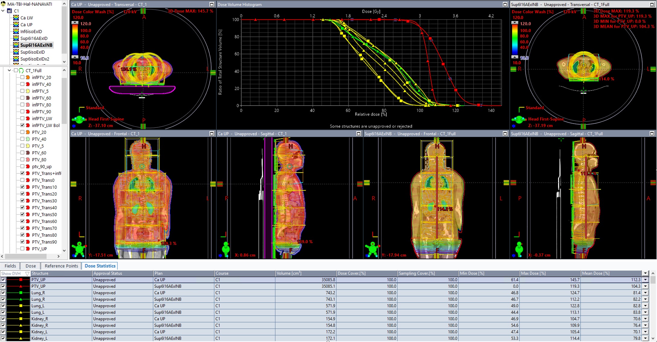
Figure1: Clinical HFS plan compared to retropecrtive re-plan with no lateral isocenter shifts, 14cm transition zone (click for full-size)
6 isocenters are placed head to foot with 14cm between each isocenter to maximize robustness with the Auto-feather feature of the photon optimizer so the entire inferior and superior potions of each arc are overlapped by their neighbouring arc. This arrangement also mimics the natural FFF beam profile with the most fluence required at the central axis of each beam leading to a more effect optimization and delivery. All isocentres are placed in a linked isocenter groups with the X and Y coordinates selected aligned to the average midline of the patient laterally and anterior/posterior such that they are midway through the thickest part of the patient’s anatomy. Due to the square primary and secondary collimators of Halcyon, 2 arcs per isocenter with collimator rotations of 0 and 90 degrees were originally selected, for a standard TBI without organ sparing this arrangement this is sufficient. However, clinically it was found for sufficient Lung sparing more than two arcs were needed and isocenters were split and a lateral shift was performed for a total of 4 arcs at the level of the lungs. However, after further retrospective analysis it was found that similar OAR sparing could be achieved without the need for a lateral shift by simply adding 2 additional arcs at each isocenter for a total of 4 arcs on those planes with the lungs. Consider 4 arcs per isocenter on planes where maximal OAR sparing is desired.
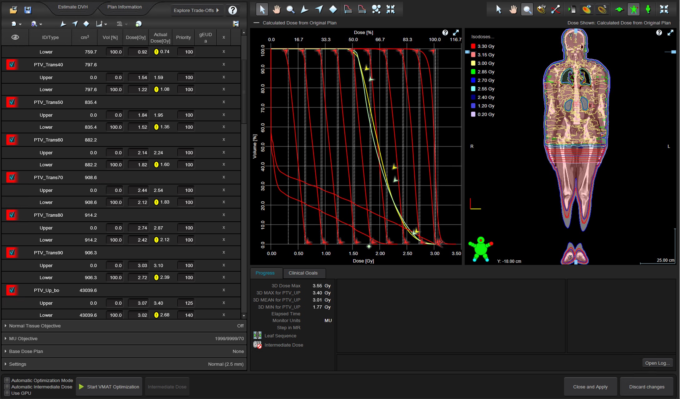
Figure 2: HFS Photon Optimizer objectives for virtal bolus optimization PTV, kidneys, lungs, and transmission zone (click for full-size)
A manual dose gradient zone is created beginning at the central axis of the 6th isocenter arc. Clinically this was divided into the following contours: (PTV 90up, PTV 80, PTV 60, PTV 40, PTV 20, PTV 5), and the same structures were duplicated to feet first Image sets and were modified/ smoothed for any additional contour imperfections. After further retrospective analysis, it was found that splitting the zone equally 1.5cm per structure starting at the central axis to the most inferior portion of the arc mimics the Auto-feather function of the optimizer and creates the most robust junction possible for the head-first to foot-first transition zone. In this case, PTV_Trans90, PTVsup80, PTV_Trans70, PTV_Trans60, PTV_Trans50, PTV_Trans40, PTV_Trans30, PTV_Trans20, PTV_Trans10 (these structures expand from the body laterally 1cm as well since they are used during optimization with the virtual bolus just as the superior PTV used for optimization). If utilizing a single CT scan head to foot this superior portion dose can be used as a base does plan for optimizing the feet first portion so there is no need to copy the transition zone structures or use them in the inferior plan optimization.
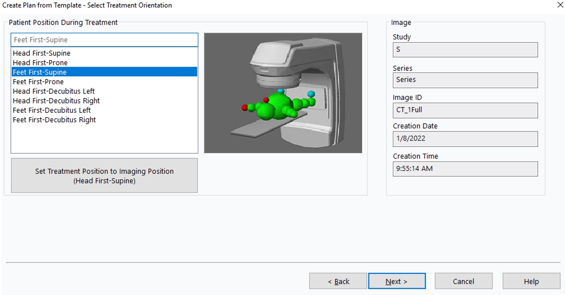
Figure 3: Insert plan template for FFS plan on the same full-body CT, just select Feet First Supine
For the inferior foot-first plan, same as the superior, 6 isocenters are placed spaced 14cm apart superior to inferior with two arcs per isocenter, collimators set to 0 and 90. The most superior isocenter is set 14cm inferior to the most inferior isocenter from the head first plan (X and Y coordinates will be the same although +/- may be flipped). Clinically, the foot-first, inferior treatment plan was done on a separate foot first scan and some iterations were required to manage the dose in the transition zone during optimization. However, during further retrospective analysis utilizing base dose during optimization is much simpler, enabled by planning both the head-first portion and the foot-first portion on the same full body CT (either with a full body scan or by concatenating both head-first and foot first scans in an additional tool such as Velocity prior to treatment planning).
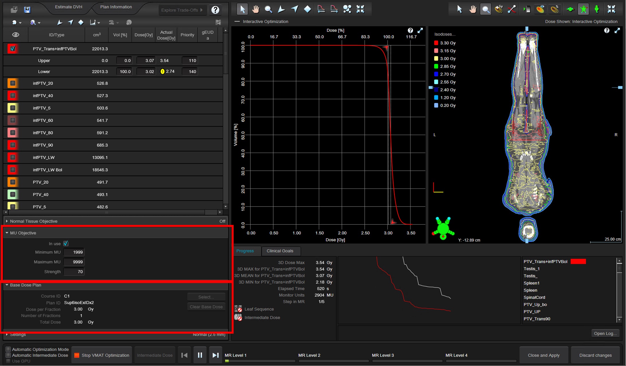
Figure 4: FFS Photon Optimizer single objective pair in combination with HFS base dose to fill the transition zone (click for full-size)
For final dose calculation, the optimized plan is copy and pasted and the 1.5cm virtual bolus is unlinked.
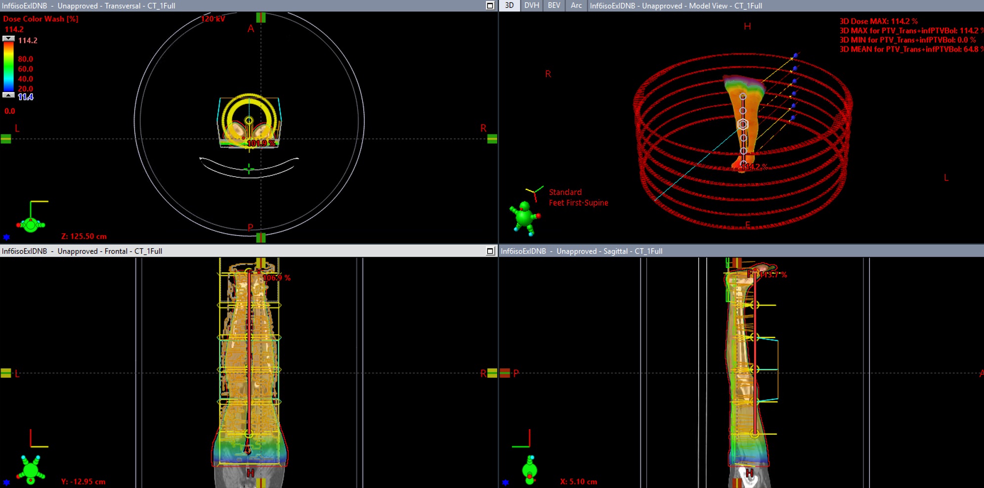
Figure 5: FFS plan after bolus is unlinked and dose is recalculated. (click for full-size)
After recalculating the final volumetric dose renormalization is required to reduce the number of Monitor Units added for the virtual bolus (which was only used to create 1cm dose margin expansion around the patient to help account for setup uncertainty).
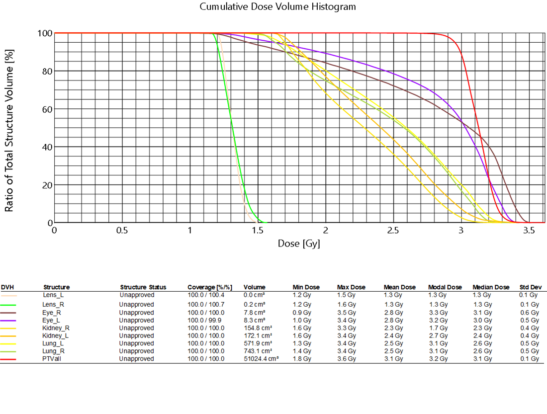
After both plans are recalculated and renormalized, they can be linked with a plan sum to evaluate.
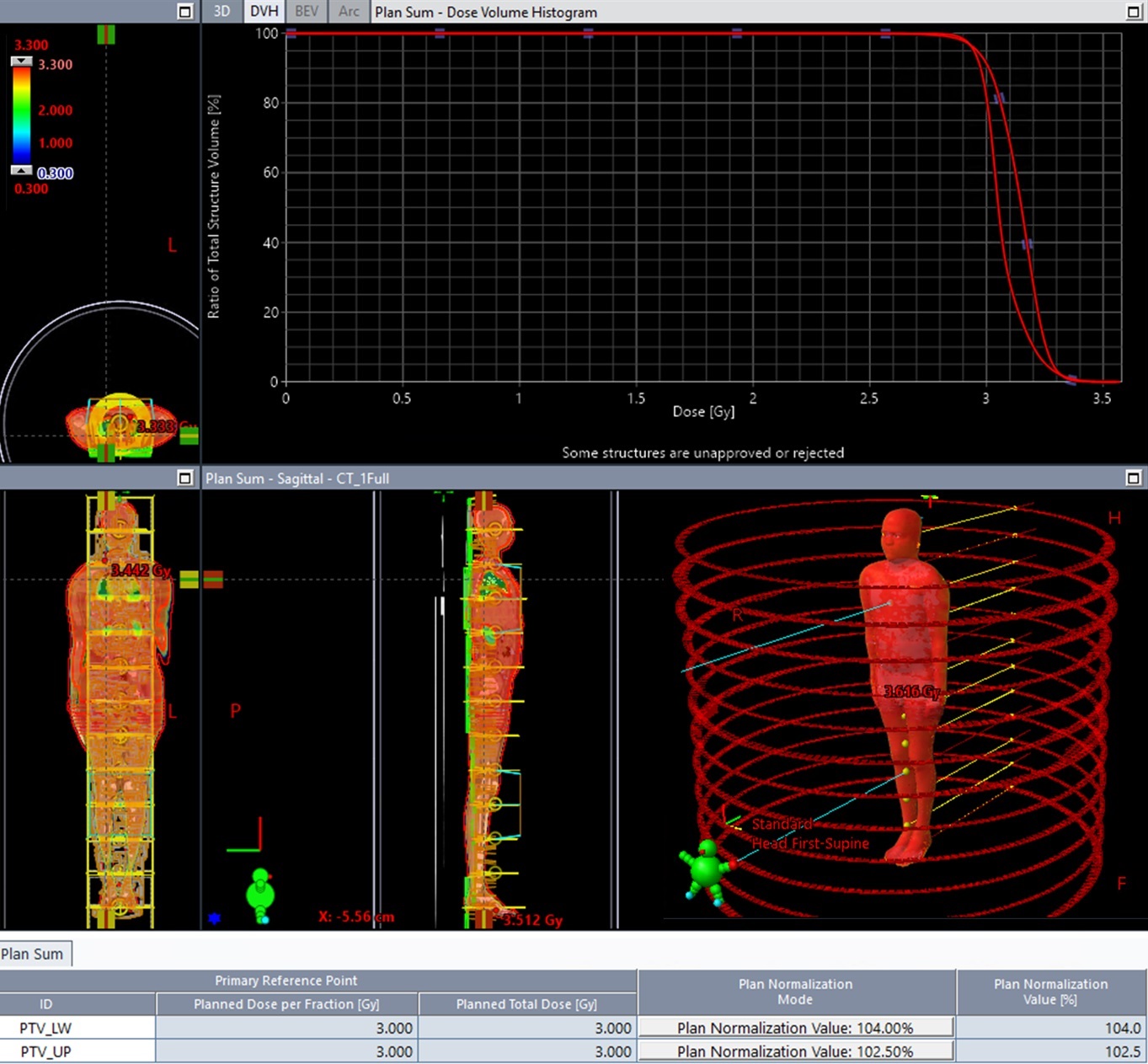
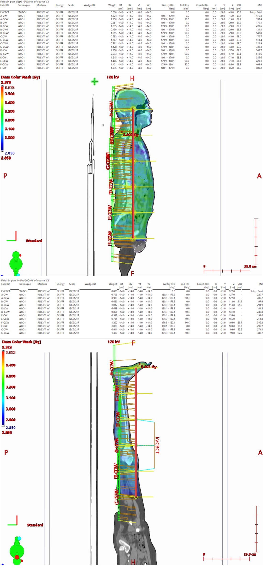
Figure 6: Plan sum, both the superior and inferior dose, isocenters and different plan normalizations required. (click for full-size)
After evaluation, the current workflow is to copy/paste each plan 6 times and delete all but one isocenter, add a KVCBCT and treatment approval each plan for delivery.
Key points for best TBI treatment planning results:
-Changing the Photon Optimizer convergence mode to “On” or “Extended” and set MR3 return
-Concatenating both the foot first and head first CT scan into one image series using velocity and utilizing “base dose plan” to fill in dose for the foot first plan optimization
-Utilizing a higher Minimum MU during optimization (min MU 1999, max MU 9999, strength 70)
-Only utilizing 0 and 90 collimator rotations
-Utilizing a 14cm head/foot distance between isocenters
-Building the manual robust junction dose ramping target structures in the Head First/Foot First transition zone
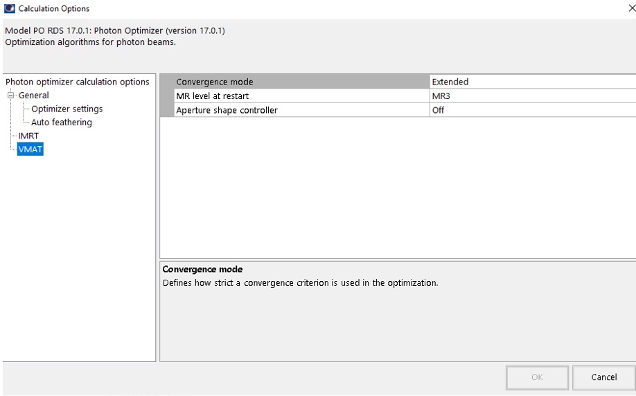
Figure 7: Convergence mode “On” as a minimum, “Extended” for additional optimzation time and quality (click for full-size)
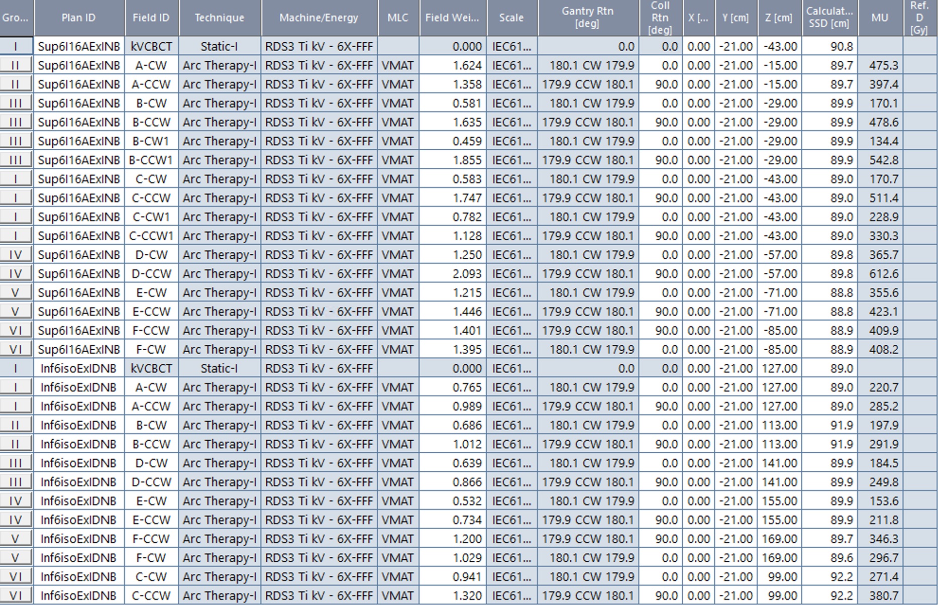
Figure 8: Plan sum field list showing 12 total isocenters placed 14cm apart in the head to foot (Z) direction (click for full-size)
Discussion:
Due to current Halcyon treatment delivery workflow each isocenter is treated separately and requires the user to enter the room to unload and reload the patient between each isocenter. In the future treatment delivery time and ease could be improved if a dedicated multi (>2) isocenter treatment workflow was implemented for Halcyon. Furthermore, in Eclipse, the Eclipse Application Programming Scripting Interface (ESAPI) could be used to accelerate the treatment planning. Two obvious potential ESAPI solutions: 1) automatically create the 10 target structure strips required for the manual robust junction in the head to foot transition zone. Or alternatively: 2) Place all isocenters on the full body CT and optimize with Auto-feather the entire plan, including the transition zone, then use an ESAPI tool to “flip” the control points for each isocenter that will be treated in the Feet First Supine (FFS) Orientation and copy them into new plans(s) marked for FFS.
The use of a 1.5cm virtual bolus and an optimization target that extends 1cm outside the patient’s body contour decreases the chance any part of the patient will go untreated due to a minor setup error. Also, placing isocenters 14cm apart head to foot and utilizing the Auto-feather feature of the photon optimizer creates a volumetric dose distribution which is very resistant to small deviations in isocenter shifts in the head to foot direction. However, again, a multi (>2) isocenter treatment workflow on Halcyon which did not require trips into the treatment room between isocenter would be very helpful. A simple “align, treat, shift, repeat” implementation could be supported by Varian in a future Halcyon software release as a specific workflow for these Total Body Irradiation (TBI), Total Marrow Irradiation (TMI), or Cranio-Spinal Irradiation (CSI) type treatment plans which require dose delivery via >2 isocenters with these robust techniques.
|
Clinical Perspective Whitepaper |
DICOM patient export |
Any reference to a "plan study" are simply what the organizers call each case and may not be a "study" in the FDA sense as they may not have been published in a peer reviewed journal.
Varian does not provide medical advice and these are illustrative examples only.
Leading plans by expert planner. Your results may vary.
FOR EDUCATIONAL AND SCIENTIFIC EXCHANGE ONLY – NOT FOR SALES OR PROMOTIONAL USE.